Quick Links on This Page
So you want to how the restoration of the
Front Axle
for my E-M-F Automobile is going?
Well, you have found the right page.

Sunday, July 22, 2012 6:47 PM
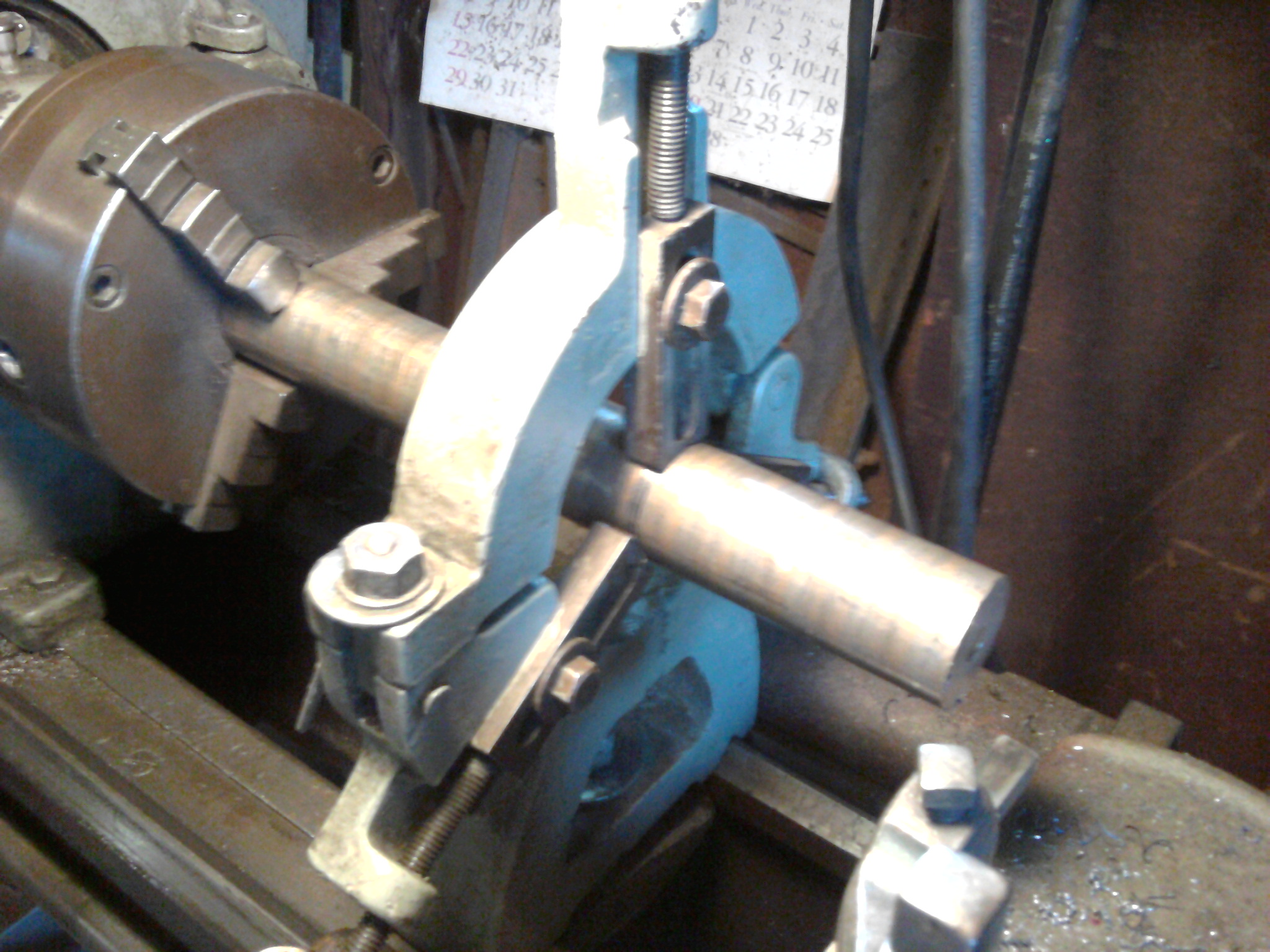 |  |
| Step 1 - Chuck up the Bronze Hollow Bar in the Lathe and set up the steady rest. Click on the picture to see the full size. | Step 2 - Cutting the smaller diameter. Click on the picture to see the full size. |
I had bought a piece of Bearing Bronze Hollow Bar to make the bushings out of. I found it on line at http://www.onlinemetals.com/. Step 1 was to chuck up the hollow bar in the lathe and set up a steady rest. My firs task was to cut the Outer Diameter of the thrust surface. Step 2 was to cut the small diameter which goes into the spindle.
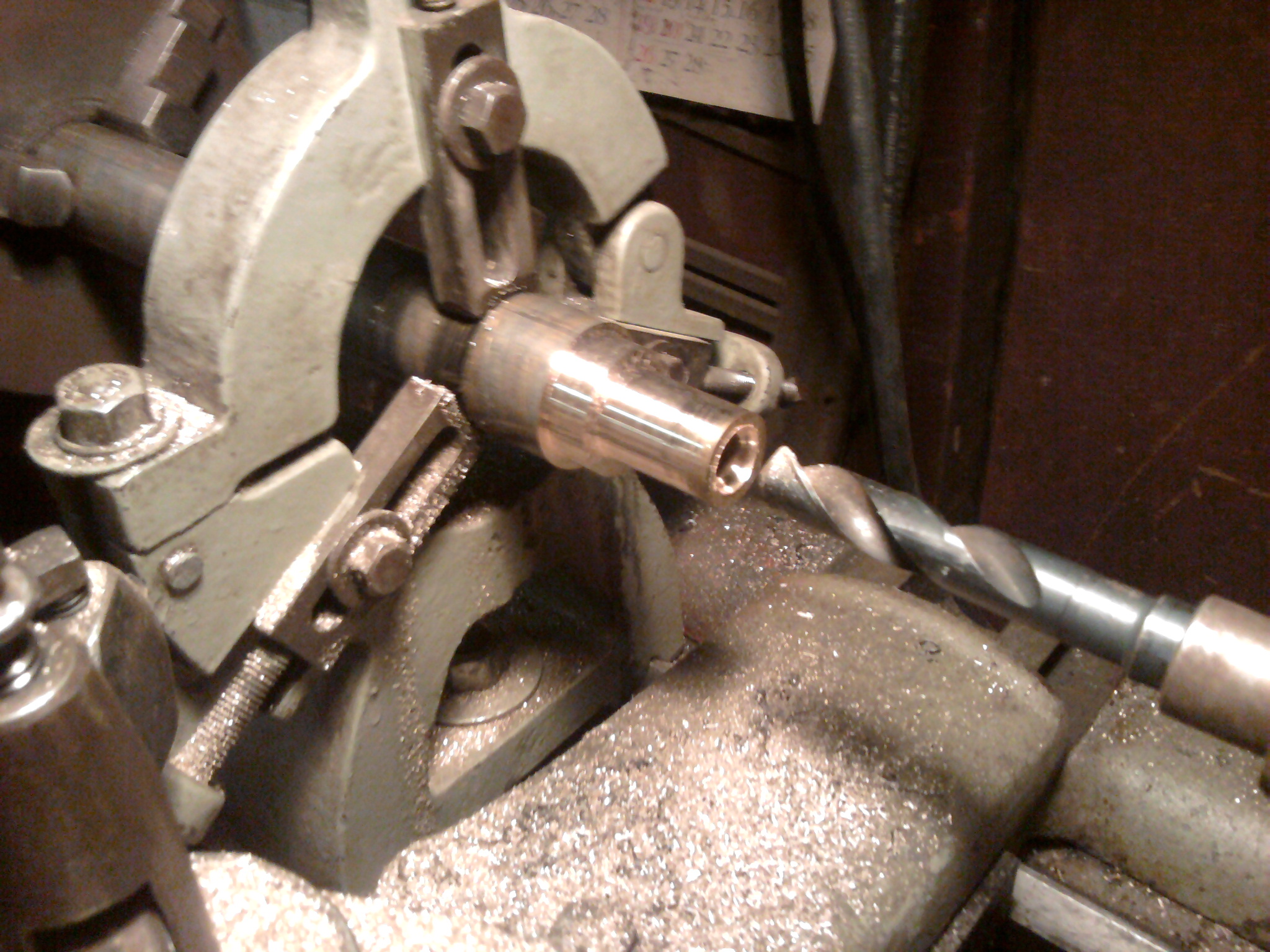 | 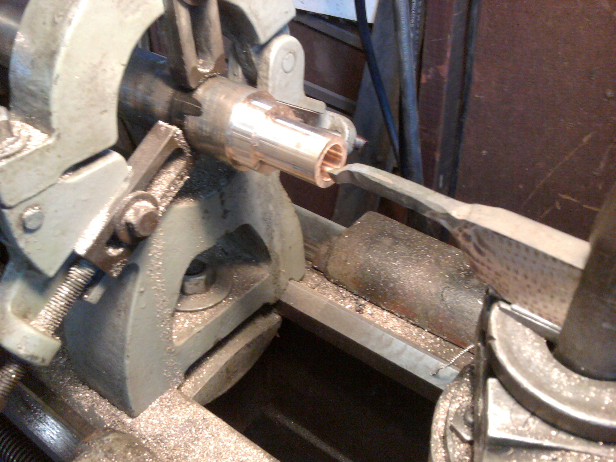 |
| Step 3 - Drill the hole out to 5/8 inch. It was the closest drill bit I had. Click on the picture to see the full size. | Step 4 - Use a boring bar to enlarge the hole to just shy of the size of the kingpin. Click on the picture to see the full size. |
Step 4 was to use a boring bar to enlarge the hole untill the kingpin would slide in up to the bearing surface, but not onto the bearing surface.
 | 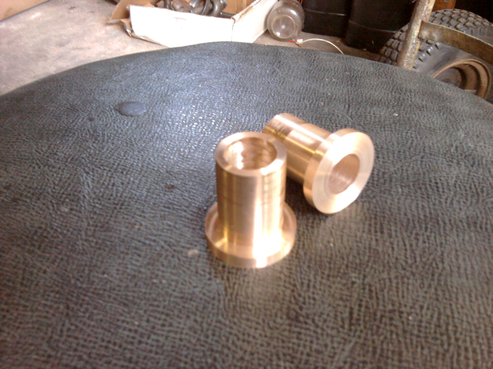 |
| Step 5 - Facing the thrust surface Click on the picture to see the full size. | Step 6 - Two bushings done and ready to install. Click on the picture to see the full size. |
You can see by the Step 6 picture the first two bushings I completed.
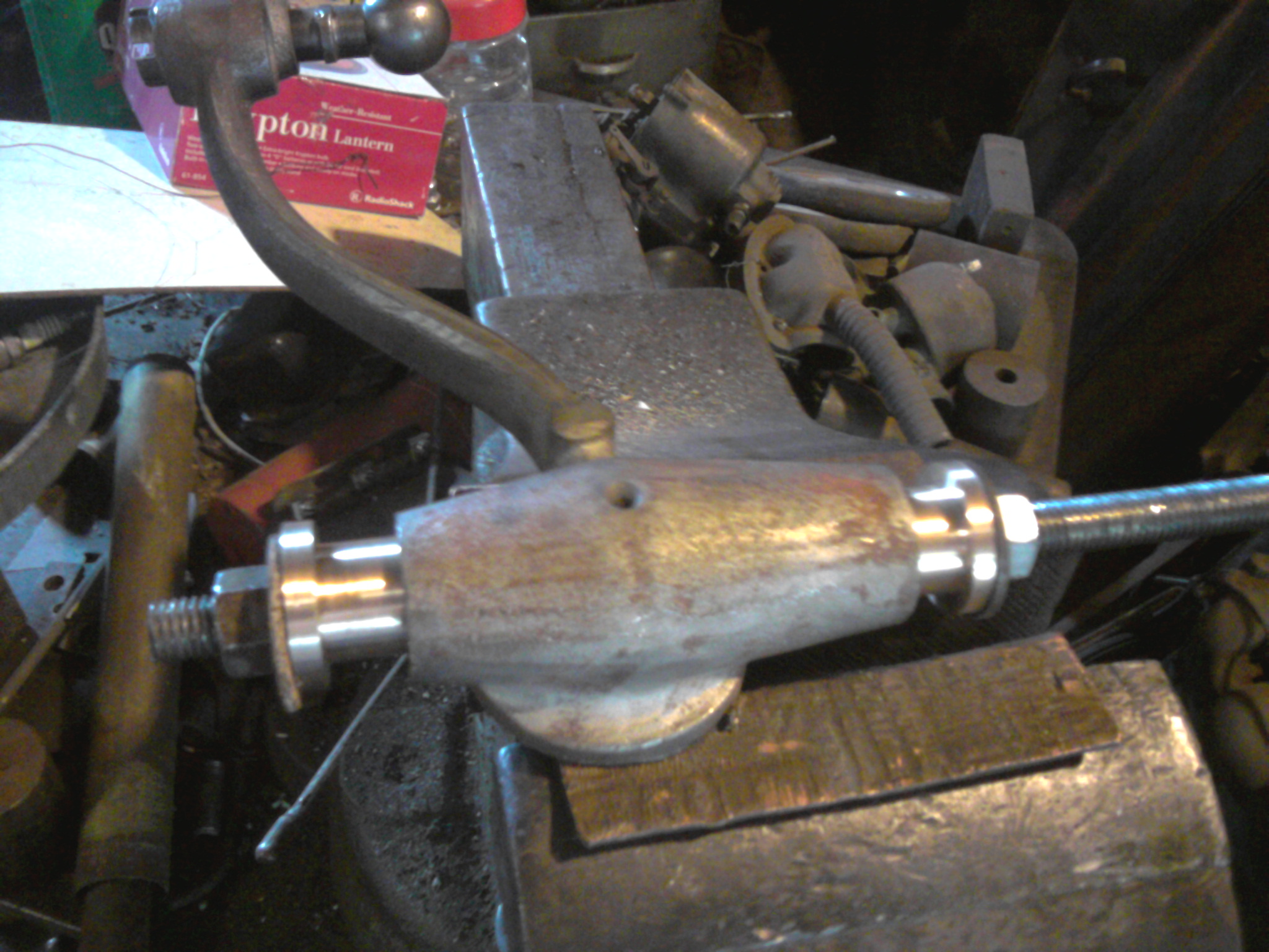 | 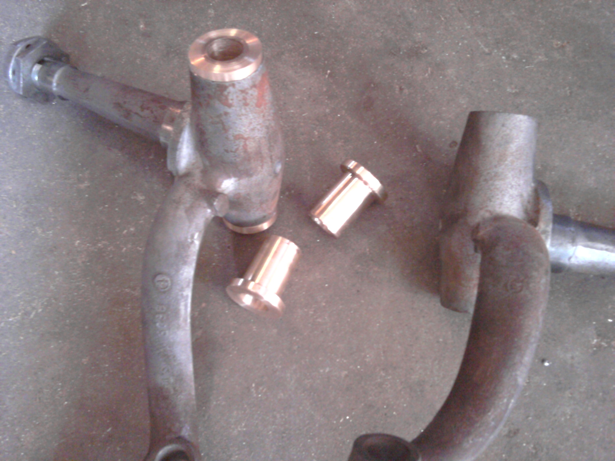 |
| Step 7 - Installing the new bushings into the spindle with a piece of all-thread, some washers and nuts. Click on the picture to see the full size. | Step 8 - All bushings done, and ready to install final two into spindle. Click on the picture to see the full size. |
Step 8 shows the final two bushings ready to install.
Step 9 was to ream the new bushings using an adjustable reamer. I reamed them so that the kingping would go in but still be tight. The next step was step 10 which was to use the Sunnen hone to final fit the bushings.
This was a fun project which allowed me to learn how to use a lathe, something I have always wanted to do. It was more fun than I can explain. A little boring perhaps at times, but I had some great company stop by to keep me company (John, Kris and Parker) and give a much needed break.
So another small step toward completing this project.
 |  |
| Step 9 - Reaming the new bushings to fit the kingpins. Click on the picture to see the full size. | Step 10 - Honing the new bushings for that final fit. Click on the picture to see the full size. |
Monday, June 10, 2013 9:04 PM
 | 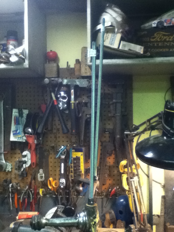 |
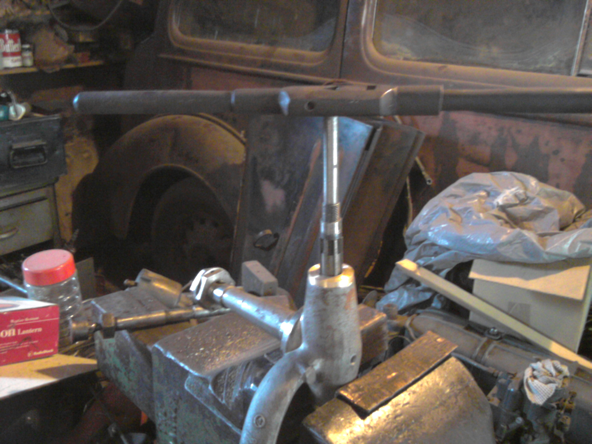
| This is the tool I made to check the alignment of the spindles. Basically just some 1/2" Nuts turned down to a cone shape to go on some 1/2" all-thread. Click on the picture to see the full size. | This shows the all thread in a spindle and showing obvious alignment problems. Click on the picture to see the full size. |
I have been trying to get the tie rod bolts to fit again and have been having a binding problem. The spindle King-pins are fitting real nice, but when I put in the very sloppy tie rod bolts, I am having binding when I turn from one extreme to the other.
I determined that I had to have an alignment issue between the king-pin and the tie-rod bolts. But how do I determine it?
I decided to make up a tool to be able to see an alignment issue. My tool consisted of two peices of 1/2" All-Thread, and some 1/2" nuts to screw onto the rod. I turned the nuts down to a cone shape so that the rod could self-center itself in the King-Pin opening and the Tie-Rod Bolt Opening. See the First Picture above.
When I put the tool into the spindle, the alignment issue became glaringly obvious. See the second picture above
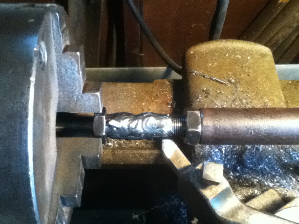 |
| Tie Rod Pin in the lathe, welded up and ready to be turned down to the right size. Click on the picture to see the full size. |
I corrected this using a monkey wrench and some muscle to bend the tie-rod arm of the spindle untill everything lined up. When I put it all back together, everything turned as it should with no binding.
The Tie-Rod Bolts were quite worn, so I first reamed out the holes back to round, then built up the bolts with a welder and turned them down to the correct size to fit the holes. See the picture to the right
In order to hold the bolt in the lathe securely, I made a peice to screw the bolt into, which had a place for a tail-stock center to hold things in place. In all, the whole front end turned out great. It is completely mechanically restored now. Just need to sand-blast and get into primer.
Thursday, July 4, 2013 7:42 PM
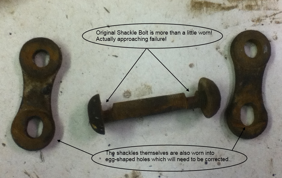 | 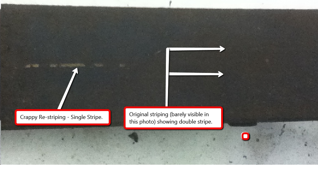 |
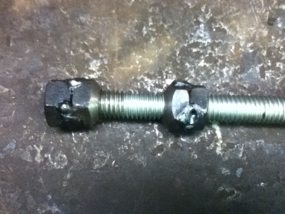
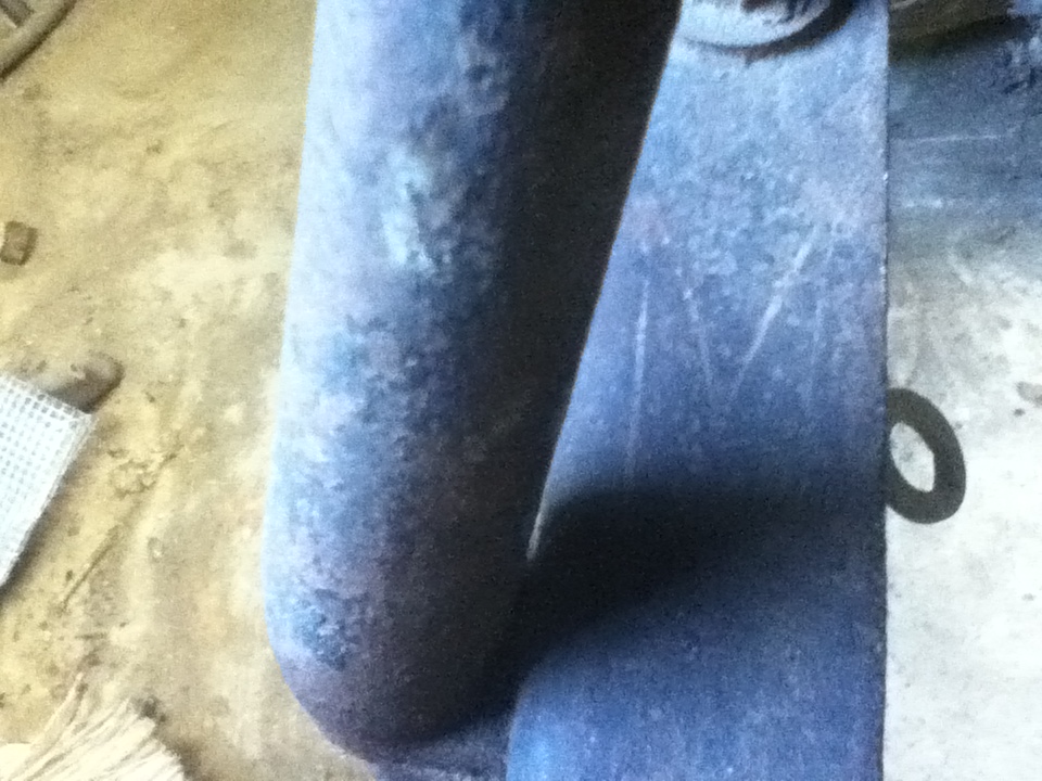
| This picture shows one of the spring shackle bolts which was obviously stuck in the spring, thus wearing grooves in the bolt to almost the failure point. Click on the picture to see the full size. | If you look really close, you can see the original striping in addition to an obvious re-stripe. Click on the picture to see the full size. |
I am so glad I took part in the group of E-M-F Owners who went together to have new shackle bolts made. This will save me a lot of time. I am hoping the project will be complete and I will get the new bolts in the next couple of weeks.
For the shackles themselves, I pulled out the front spring shackles from the Nebraska parts chassis, and it looks like I have enough of the threaded shackle parts to put together a set, and I will have to weld up the non-threaded sides to get two good ones.
Once I got both springs off, I went about trying to find and document the original striping. I cleaned the springs with "Simple Green" and a tooth brush. Some striping appeared immediately, but it was very confusing. What I mean is that I was seeing a single stripe down the front half of the spring and a double stripe on the back half. Continued scrubbing revealed that it appears the cars chassis was repainted at some point and re-striped. The re-stripe was not nearly as nice of a job as the original, with much waivier lines and varying thicknesses of stripes.
This actually made me feel very good, because all this time, I thought the re-stripe was the original striping, and I did not like the pattern. This also matches the striping I found on my parts chassis, which is something that has always bugged me.
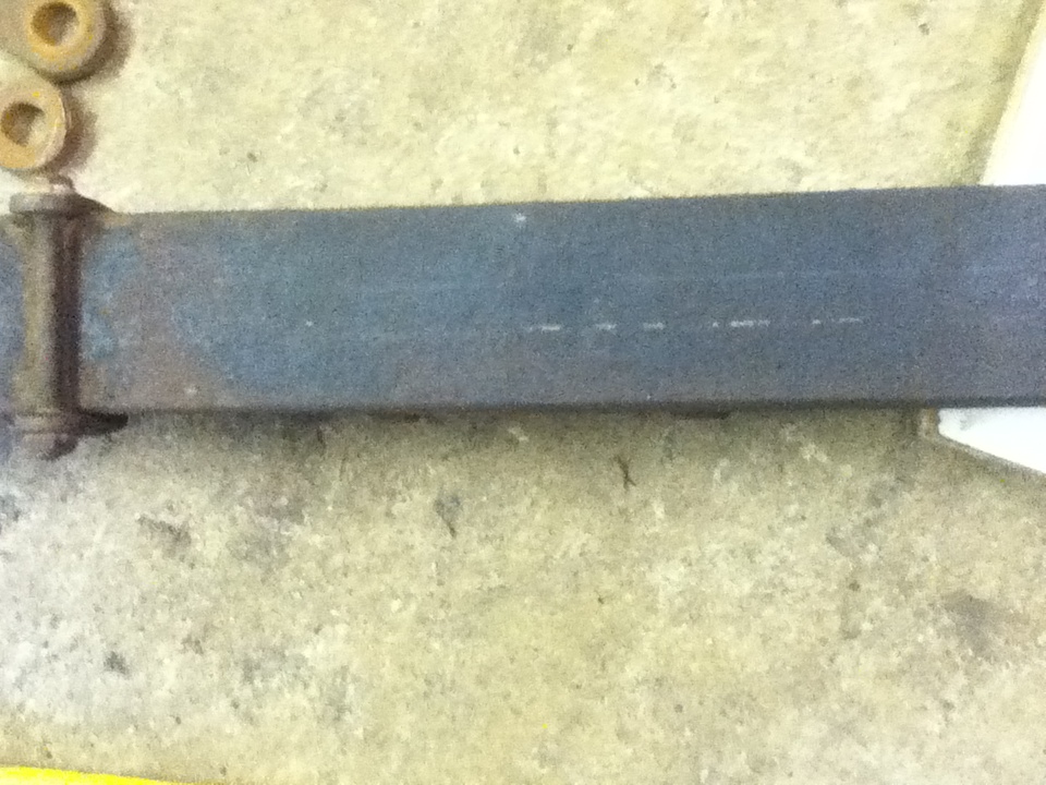 | 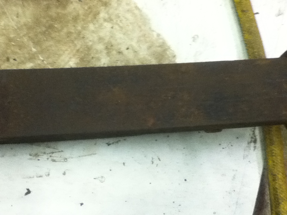 |
| You can see the original two stipes on the spring in this picture. Click on the picture to see the full size. | Another example of the original strips. Click on the picture to see the full size. |
I also found striping on the Front axle, which ended up being just a single stripe which splits out at the end.
I spend hours documenting the spring and front axle and added these two striping diagrams to the Striping Diagrams Page. Eventually there will be an entire set of striping diagrams for a 1912 E-M-F Demi Tonneau.
I also found some original striping on the front frame rails which I have not had a chance to document yet. You can see the picture on the right below.
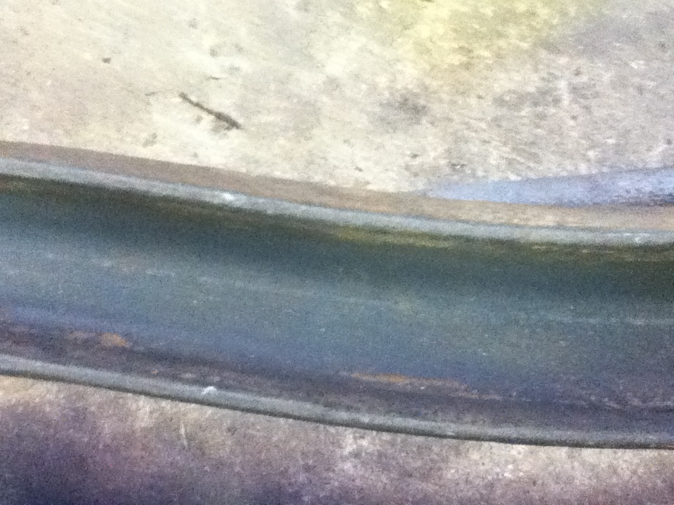 |  |
| If you look close, you can see the single stripe on the front axle. Click on the picture to see the full size. | Original striping on the front frame rail. Click on the picture to see the full size. |
Next up will be sand-blasting and priming with etching primer. I plan to disassemble the springs and clean up each leaf. I may start this weekend.
Sunday, October 13, 2013 9:21 PM
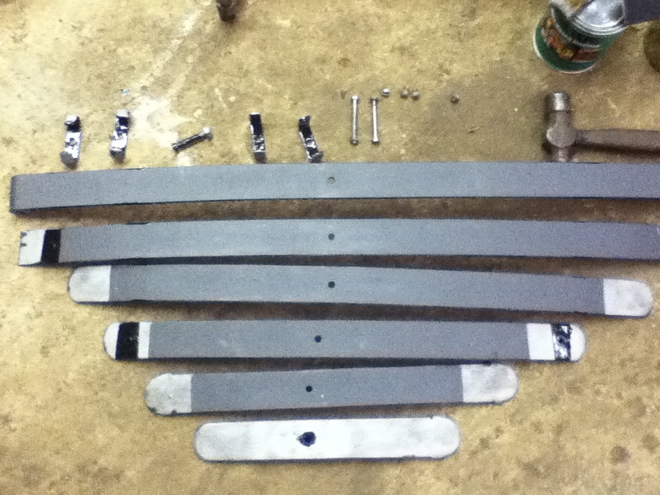 |
| Six spring leaves cleaned and painted with graphite paint. Click on the picture to see the full size. |
Spent some time today cleaning up the leaves for one of the front springs with the sandblaster and then painting the mating surfaces with Graphite paint. I also paints some of the areas of the clamps with POR-15. I need to come up with some rivets to put the clamps back onto a couple of the spring leaves. I also took the other front spring apart and started to clean it up. My back can only take standing at the Sandblaster so long, I will have to finish next time. Felt good to make some progress on the E-M-F.
Sunday, October 27, 2013 8:43 PM
 | 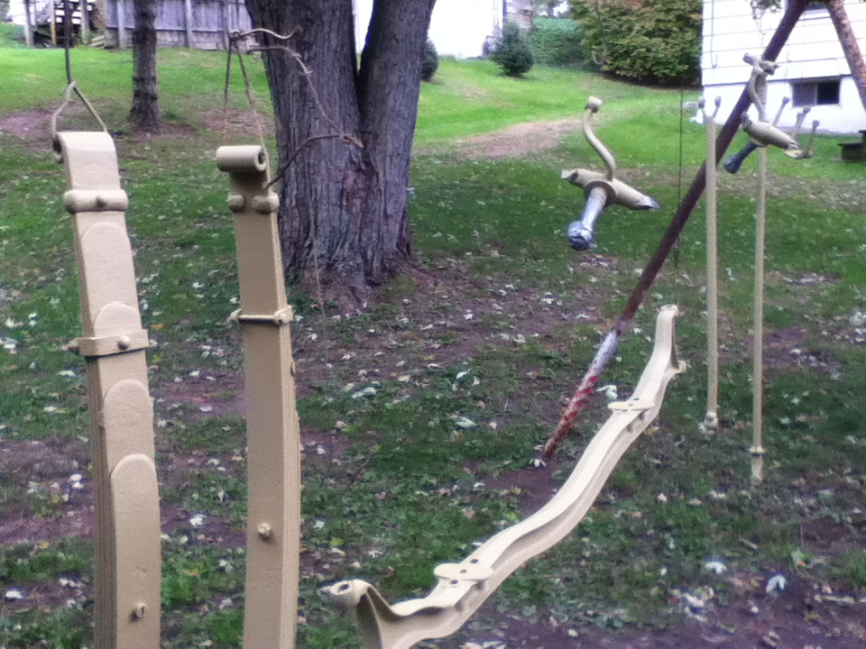 |
| Spring Leafs with brackets riveted back on. Click on the picture to see the full size. | Front End parts hanging with a fresh coat of etching primer. Click on the picture to see the full size. |
Well I have all of the Front End parts for the E-M-F Mechanically restored, in primer, and back on the car for safe keeping until the time when I will finish them in black paint and stripe them accordingly.
When I disassembled the front leaf springs, I removed 4 riveted-on brackets from each set of springs so I could fully clean them. To put them back on, I needed some new rivents. Thanks to the Internet and Google, I was able to locate 9/32 round head solid rivets which were 3/4" long. I got them from Jay-Cee Sales Inc. I ordered them on a Monday and they arrived on Wednesday. Hows that for service.
In order to set the rivets, I needed to make a tool so that I did not deform the round head when setting them. To do this I took a large piece of steel had a drilled an indent into it, then used a round nose carbide cutter in my drill press to make it round, or at least as close to the head of the rivet as possible. I then set them using a ball-peen hammer.
Next I cleaned up all the front end parts and then put a coat of etching primer on them, as you can see in the picture above.
 |
| Front End parts Back on the chassis to wait for final finishing. Click on the picture to see the full size. |
I then reassembled all the front end parts onto the chassis where they will stay until I am ready to do final finishing of them. It feels really good to see all those parts back together.
Next up I will work on the steering column and all the linkages to get them nice and tight. I removed the steering column from the car and will clean it up this week. I am taking it to Iowa with me next weekend to discuss waht to do about fixing it all with my dad. I am also taking the steering column from my parts car, which was a 5 passenger touring, so the brackets are a bit different, but I am hoping the insides are the same.
That is all for now.
How to contact me... |

|
|
John M. Daly |
||
| Phone: | (815) 786-4824 | |
| Email: | ||