Quick Links on This Page
So you want to how the restoration of the
body
for my E-M-F Automobile is going?
Well, you have found the right page.

Monday, June 11, 2001 4:24 PM
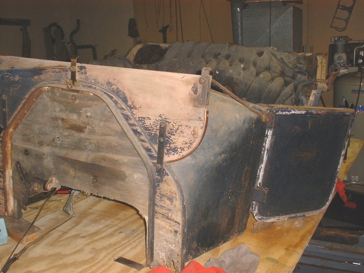 | 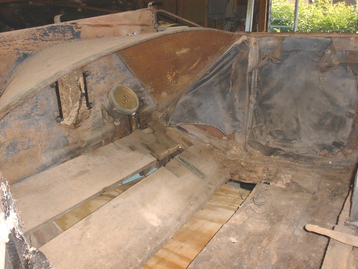 |
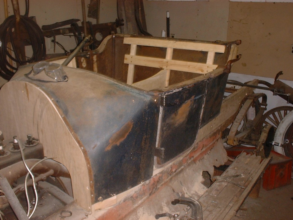
| Passenger side of body on horses showing fire wall etc. Click on the picture to see the full size. | Inside the drivers compartment. You can see the rotten wood. Still have the Speedometer on the dash. Click on the picture to see the full size. |
I have taken some time to play "puzzle" with all the pieces, but most of my time right now is being spent on repairing the Model T Engine.
I have started to remove some of the screws that hold the metal skin of the body onto the wood skeleton. This is proving to be difficult since the wood is so rotten the screws do not want to back out, and all the screw heads on the exterior of the body are leaded over. This makes a nice finished product, but a chore to remove.
I have noticed that under the ID plate on the firewall was the remains of what looks like paint, so at this point I am assuming that the firewall was painted body color. I found similar paint under where the coil was mounted on the inside of the body, so it was painted too.
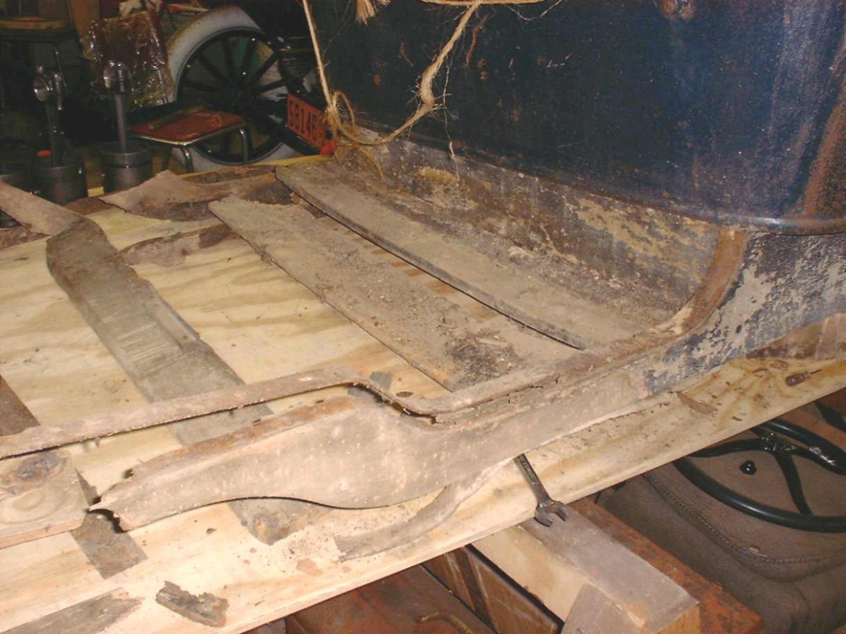 |
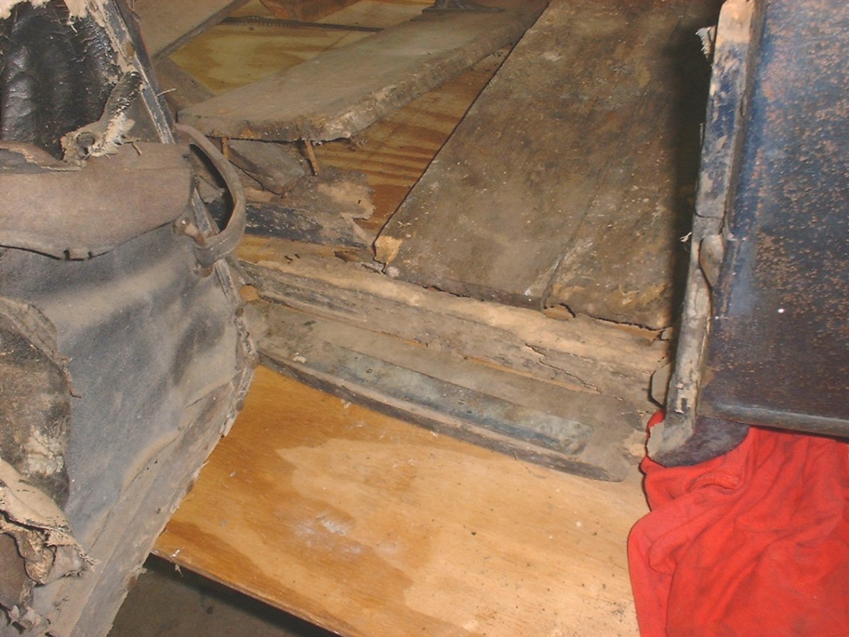
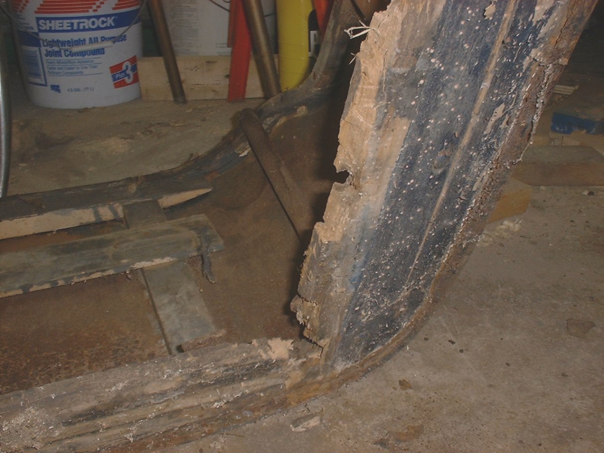
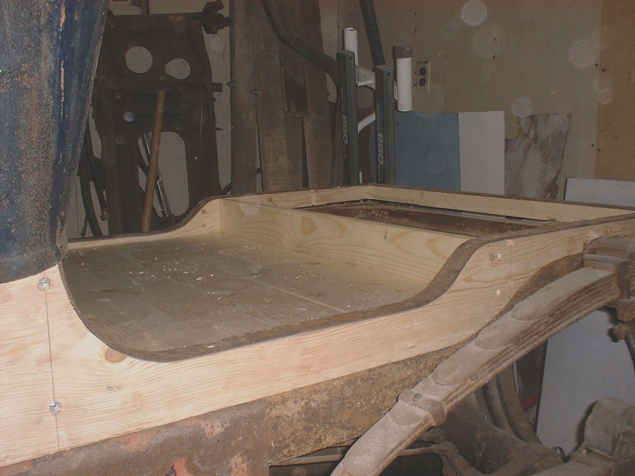
| Drivers side rear deck. I hope there is enough left for patterns. Click on the picture to see the full size. |
The deck that supports the rear seat (Tonneau) is really bad. I think there will be enough for patterns, but it will be a challenge. Notice in the pictures that there is a steel rail that runs along the top of the wood, so that the rear seat sits on top of the steel tail and not directly on the wood (Wood-to-Wood BAD, Wood-to-Steel GOOD). This gives me a shape for at least this side of this board.
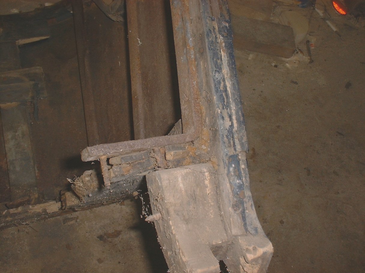
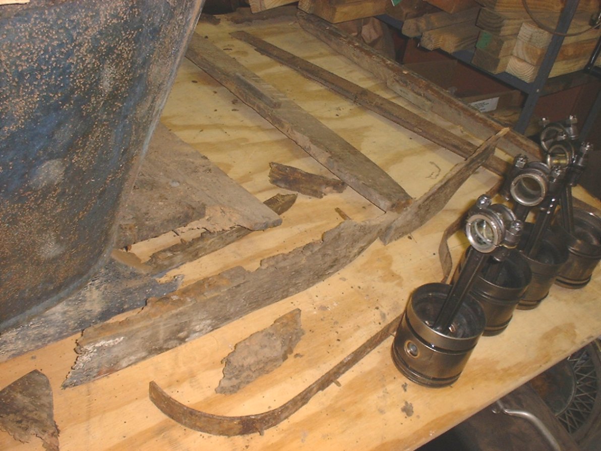 |
| Passenger side of the rear deck that supports the rear seat (tonneau). NOTE: the pistons are from my Model T. Click on the picture to see the full size. |
Monday, June 25, 2001 11:14 AM
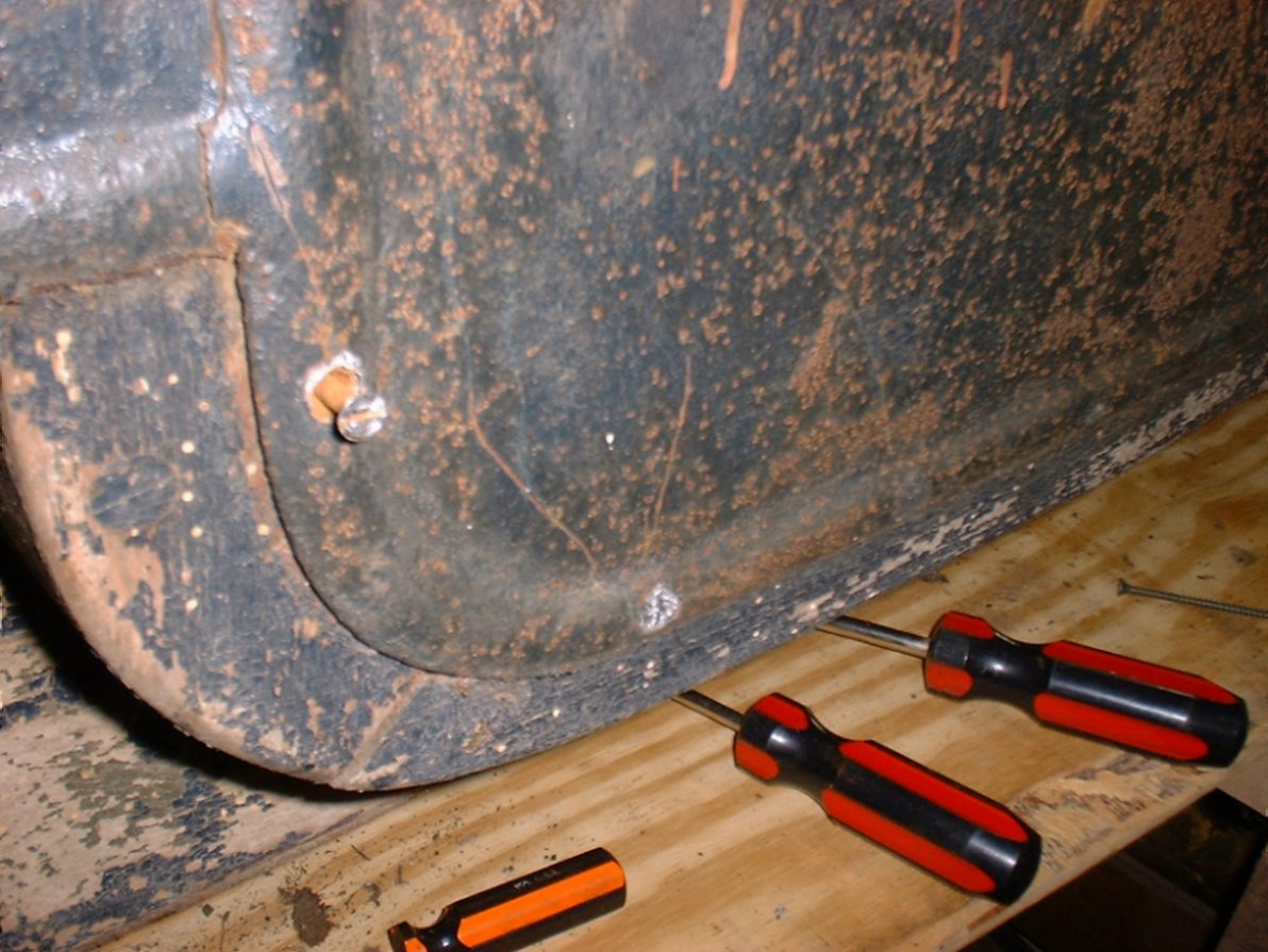 |  |
| Here are the screws that hold the body panels to the wood skeleton. All the screw heads are leaded over. Click on the picture to see the full size. | Doorsill pieces in their approximate places. Click on the picture to see the full size. |
Worked some more to remove some of the screws. I included a picture to the left. All the screws are leaded over. At this point I am just digging the lead out, and backing out the screws.
I have also been continuing my game of "puzzle" by trying to determine where wood pieces came from. I think I have the passenger side doorsill figured out. I plan to "kwik-poly" this wood so that I do not loose any more of it, then cut new pieces. For those of you who do not know about "kwik-poly" and do wood work on old cars, you need to check this stuff out.
Saturday, August 25, 2001 5:17 PM
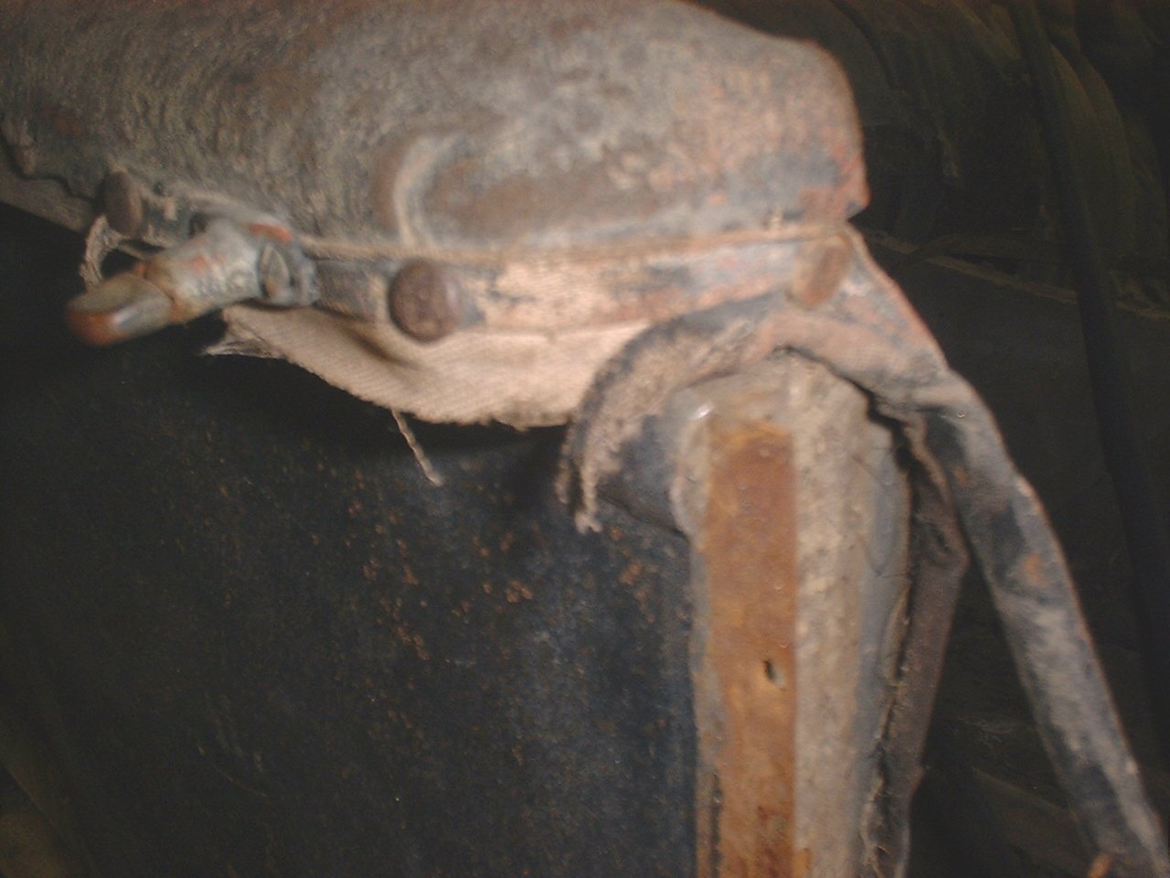 |  |
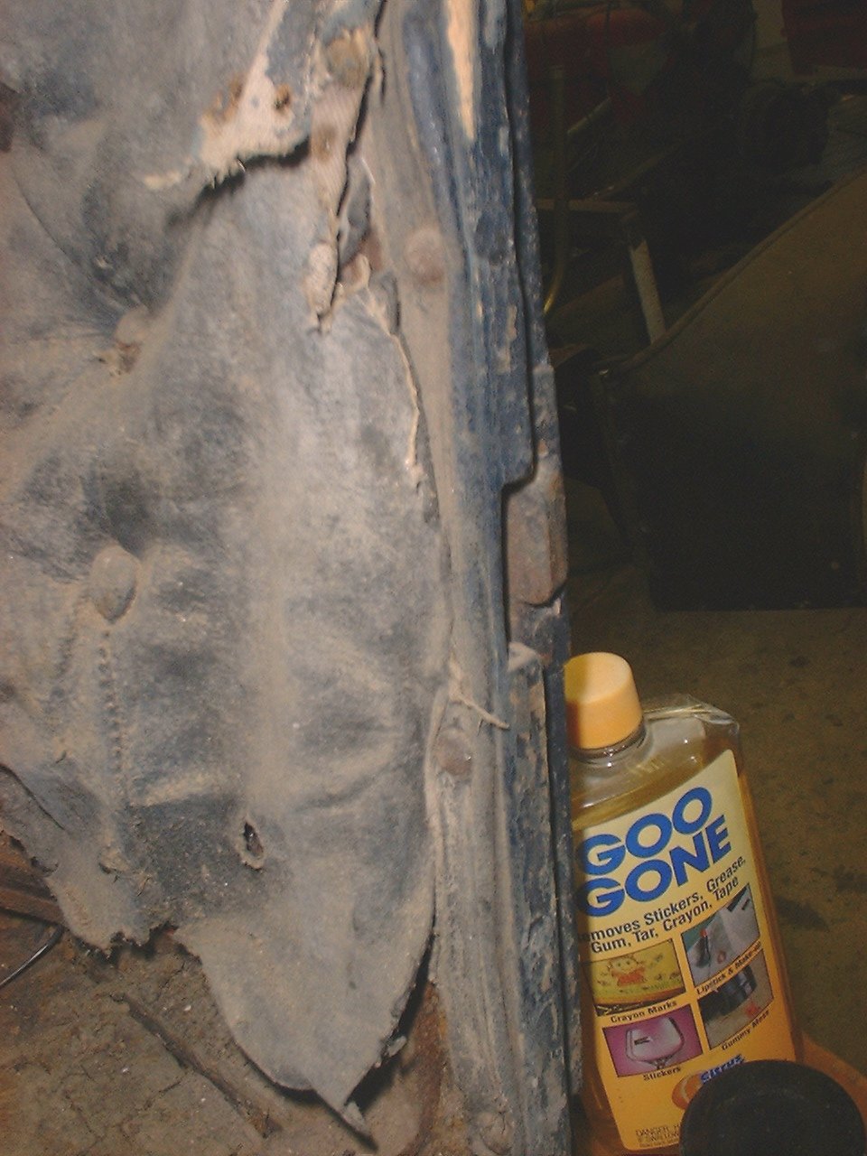
| Here is a picture of the corner of the drivers side seat arm rest. Notice how the leather is folded and tacked. Click on the picture to see the full size. | Here is how the upholstery is done around the top supports. Click on the picture to see the full size. |
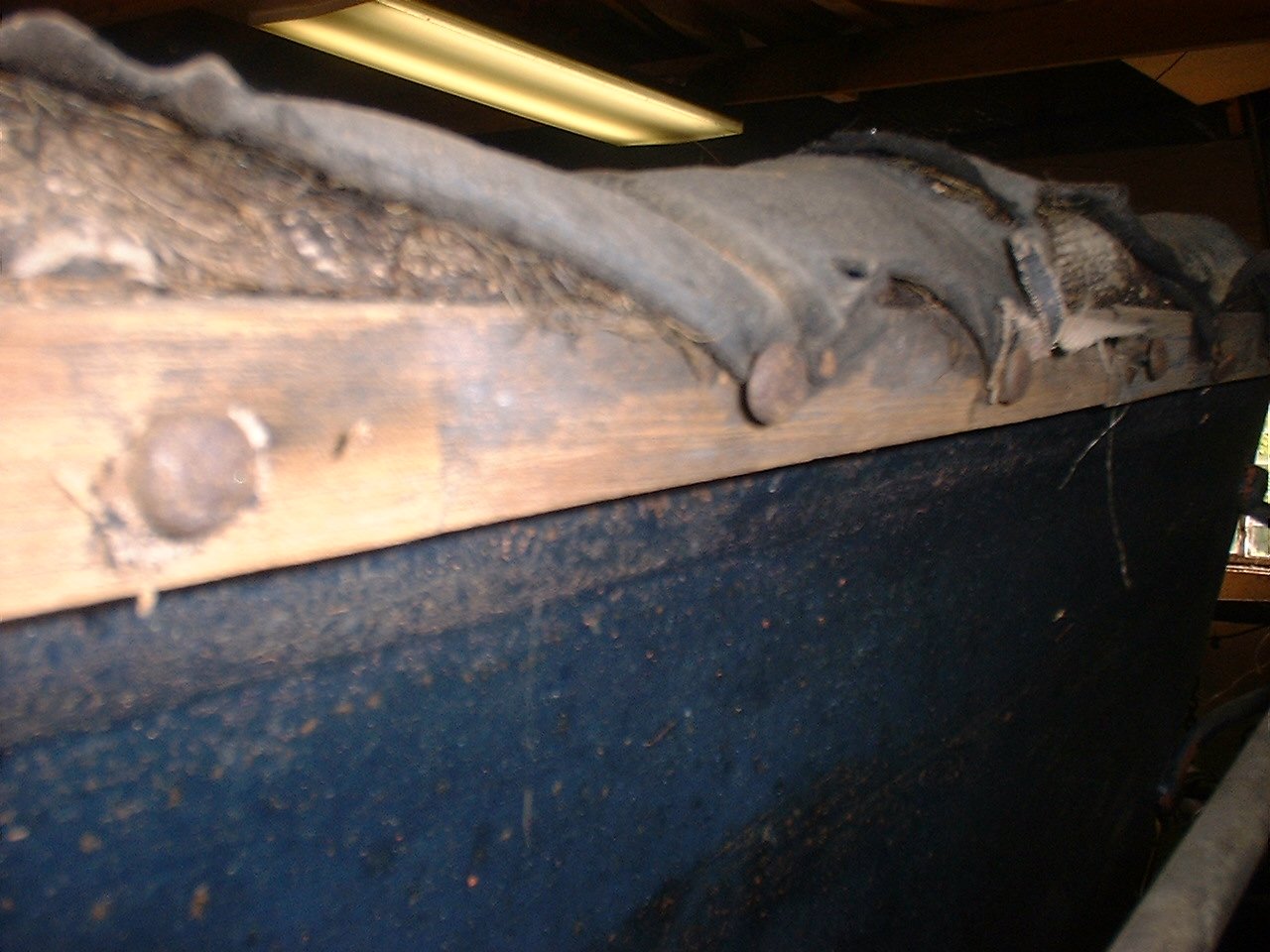 | 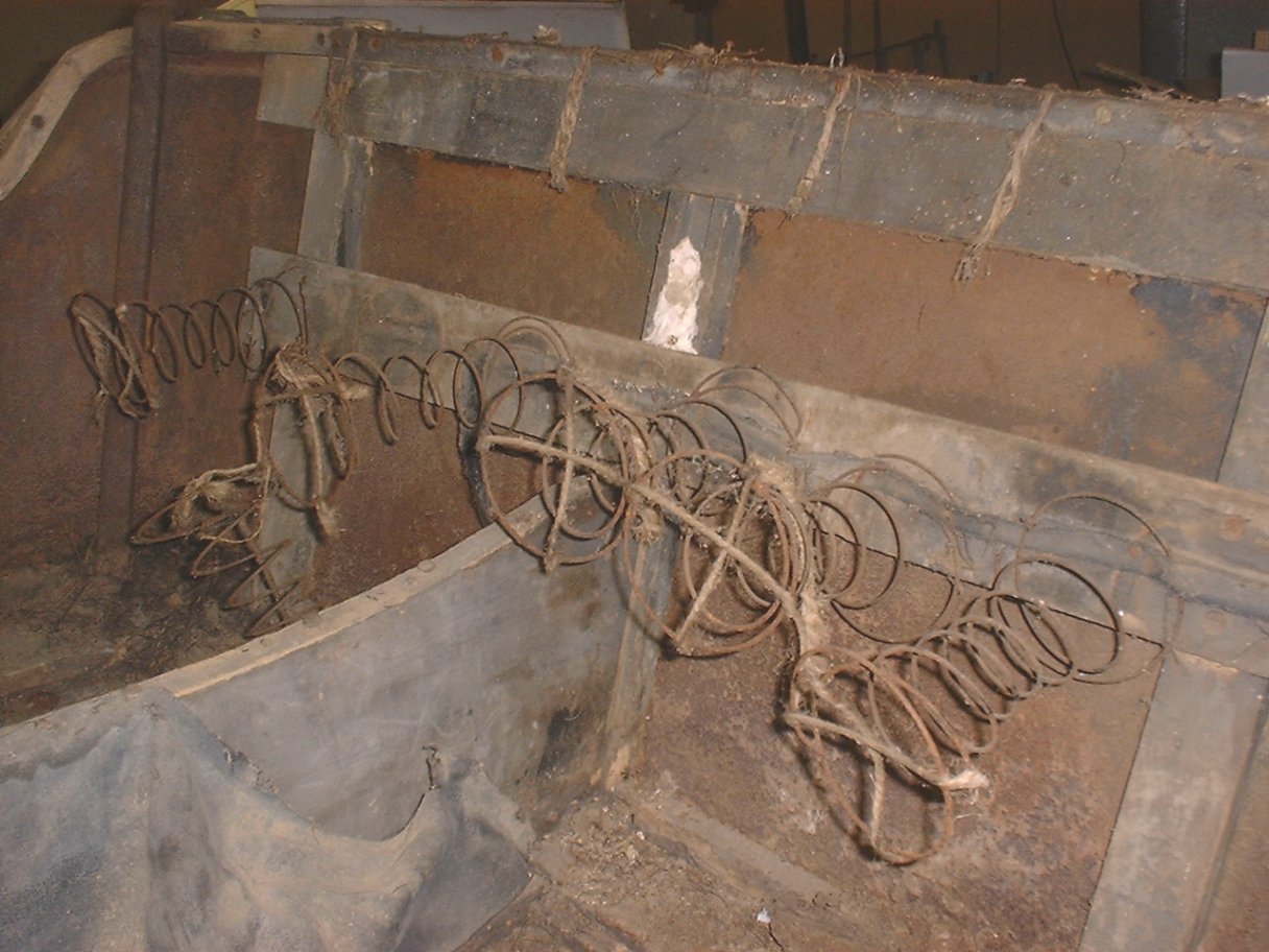 |
| Here is the tack rail along the back of the front seat. Click on the picture to see the full size. | Here are the springs for the seat back of the front seat. Notice the pieces of twine used to hold the spring in place while the upholstery was installed. Click on the picture to see the full size. |
 | 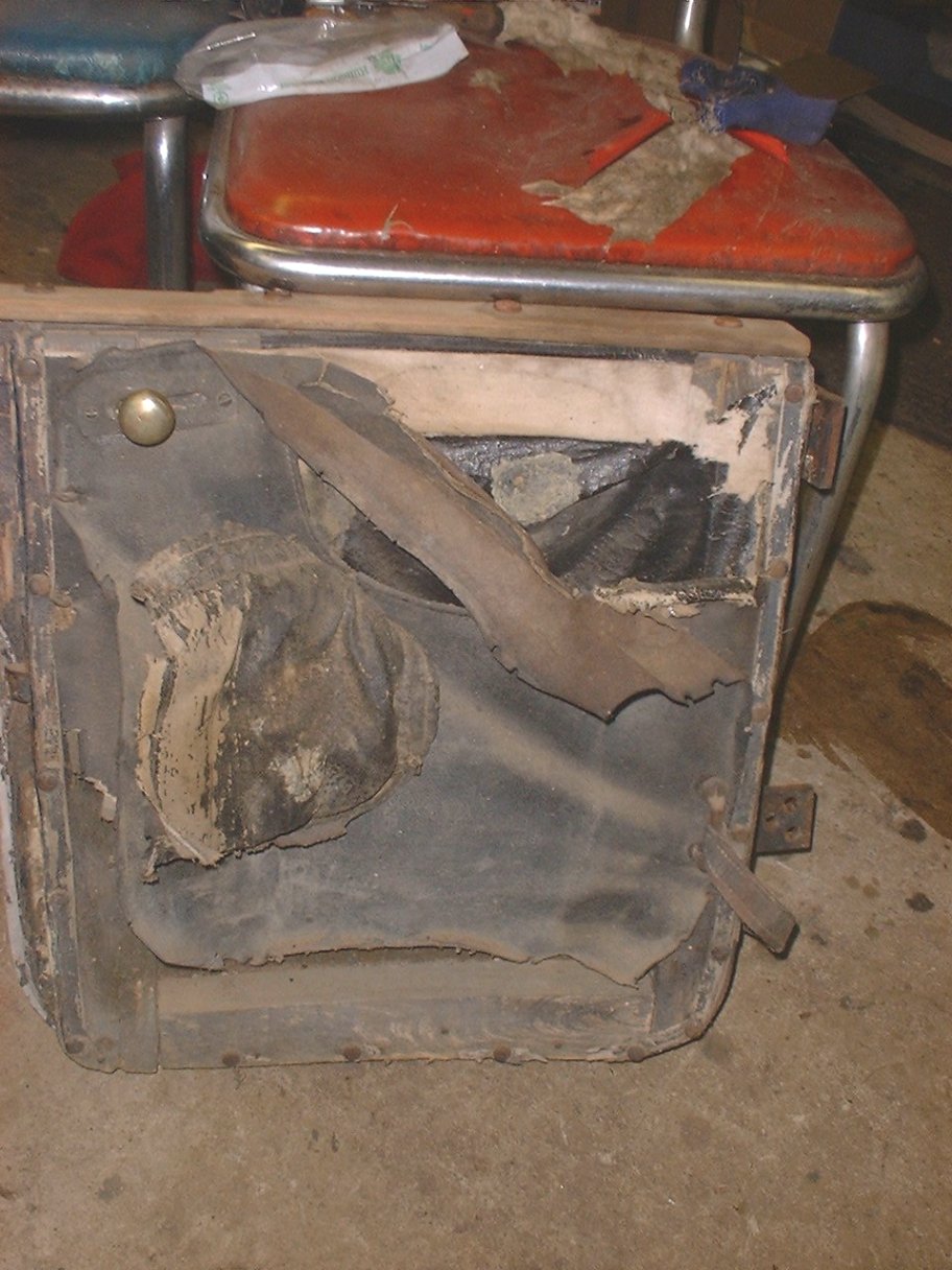 |
| This is the door jam on the passenger side front seat. Notice now the trim is tacked on to trim out the edge of the upholstery. Click on the picture to see the full size. | The front passenger side door, removed from the body. Click on the picture to see the full size. |
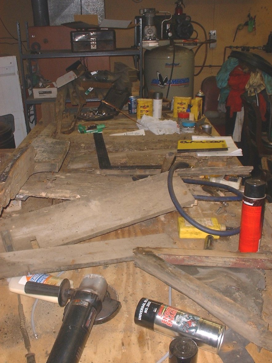 |
| A picture of what use to be the body for my E-M-F. Hopefully I will be able to figure out how all these pieces go back together. Click on the picture to see the full size. |
Sunday, November 4, 2001 5:20 PM
 | 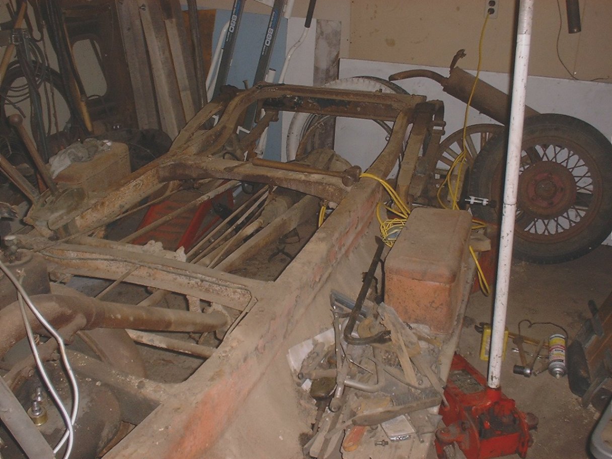 |
| Chassis read to serve as the "jig" for body reconstruction. Click on the picture to see the full size. | Rear of chassis, minus fenders, ready for body reconstruction. Click on the picture to see the full size. |
My plan from here is it remove what is left of the running boards to help me get in to where I need to be. I also want to clean up around the chassis and store a few more parts into the basement to get them out of my way. I hope to be cutting wood by Thanksgiving. We will see.
Monday, December 17, 2001 6:21 PM
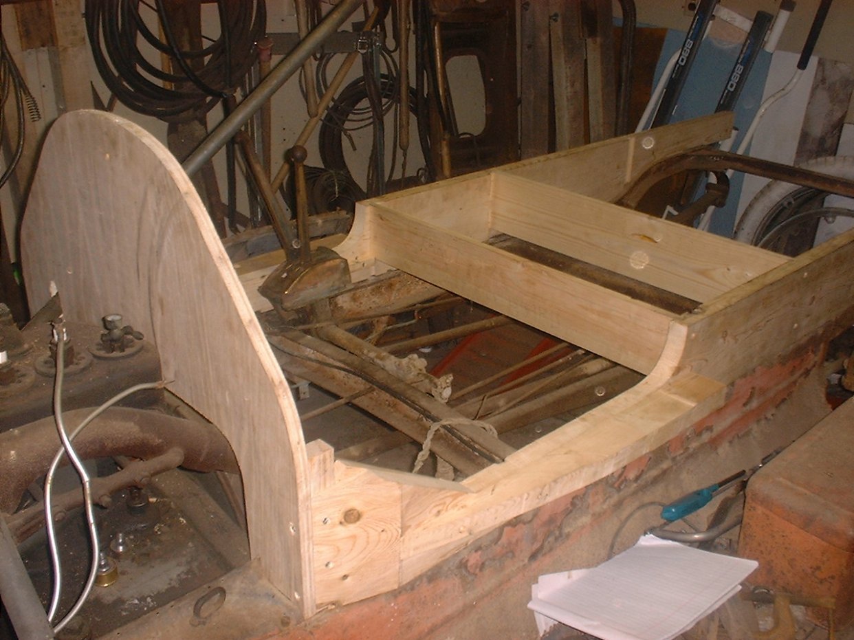 | 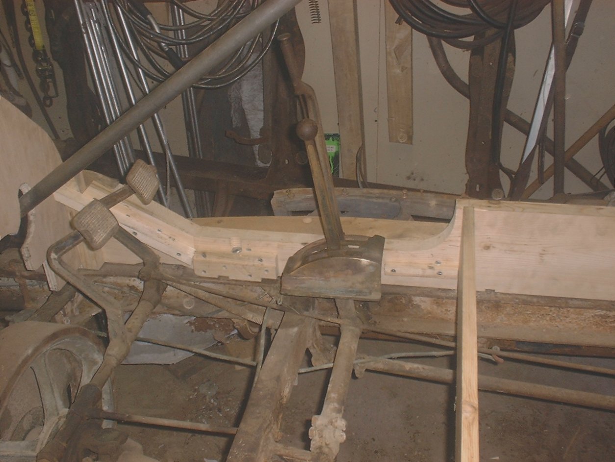 |
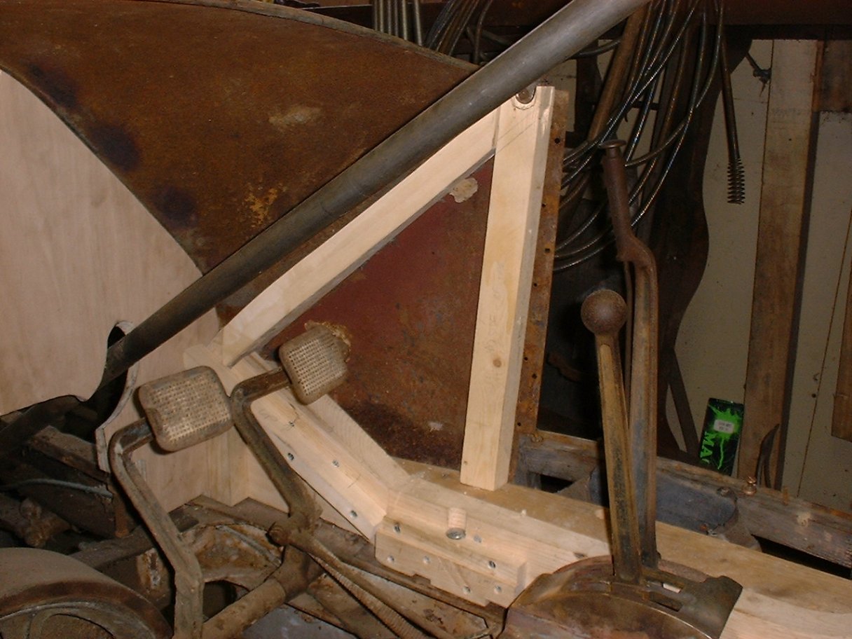
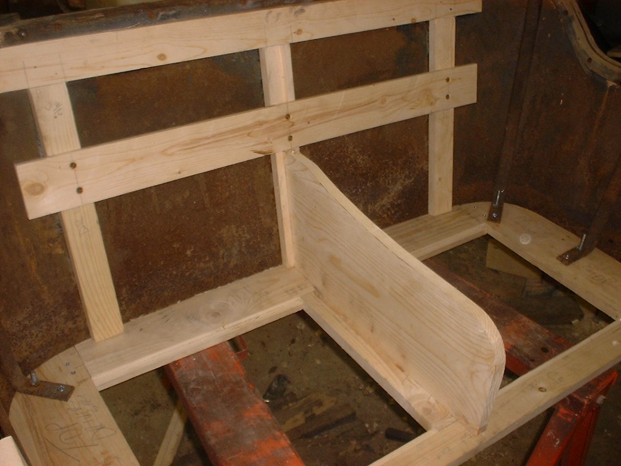
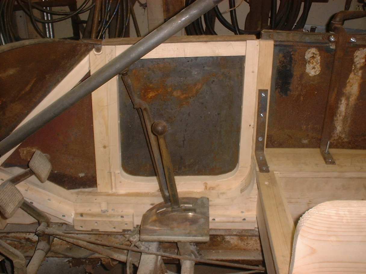
| Start of template for new body showing firewall, front seat riser and angle of front floor boards. Click on the picture to see the full size. | Control center showing floorboard supports around shift gate. Notice how a floorboard support it build into the shift gate. Click on the picture to see the full size. |
On the Friday after Thanksgiving, I went over to my Friend Andy Dowiarz's house with 2 - eight-foot pine 2x8's with the intention of planing them down to size with his planner and rough cutting the curve for the frame on the band saw.
Before writing me to tell me not to use pine for the body, let me remind you that my plan is to fabricate the new body first out of pine and then rebuild it out of ash. I have several reasons for this:
1. - What wood is left from my body is so badly deteriorated that is good for a visual pattern only. If I were to use it to cut the new wood for the body, I would have a big mess when I was through.
2. - Doing it out of pine first will allow me to figure out the best order in which to cut the wood to make best use of the scraps for things such as floor board supports.
3. - I would much rather make a mistake cut on a $5.00 piece of pine than a $70.00 piece of ash (which I have already done...keep reading).
So back to the story. I planned the 2x8'x down to the correct thickness (1 3/8" I believe) and also cut them for the height of the front seat riser (7" I think). Once back in my garage, it was time to fit the 2x8's (I will call "main rails" from hear on out) to the frame.
The first thing I did was make a mark on the boards where I wanted the front body mount bolt to be. I chose a point that would force me to have to fit the main rails to the "S" curve of the frame. Remember, I am following Don Marshes rule: "Work from the fire wall back and the frame up."
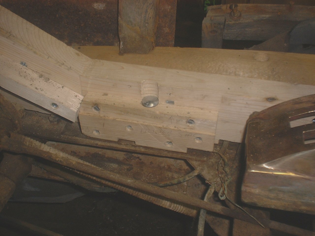 |
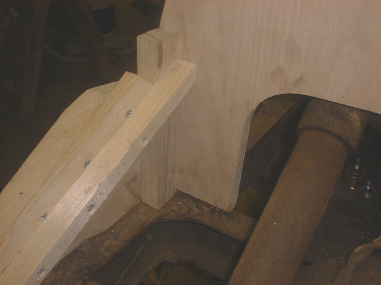
| Front body support. NOTE how hole is half in the main rail and half through the two blocks screwed into the main rail. The head of the carriage bold does recess further into the floor board support. Click on the picture to see the full size. |
After getting the front mounts set up, I then fit the boards to the frame, chiseling out recesses for each rivet head, bolt etc. I also had to cut a circular recess on the side of the main rail 1 3/4" in diameter to fit around the rear spring hangers.
After the main rails fit the frame, I wanted to get the front and rear kick boards for the front seat in place. This would establish the width of the body and give it some support. I used the front bolt holes for a reference and measured back on the original rails to the front kick board. I also took the same measurement on my neighbors E-M-F. I laid out the cut and set up my sliding crosscut miter saw to make the cut (do not have a radial arm, so I modified my miter was for a depth adjustment). I also cut a dado for the rear kick board for the front seat. Unfortunately, I made the wrong measurement for one of these cuts and made the dado in the wrong place. Luckily this is only the template. I would have been pretty mad if I had been cutting this out of ash. I corrected this by just cutting the dado in the correct place at a slightly deeper cut.
Next up was fitting the firewall. I cut the firewall using the original as a template, but adding on a little so I could trim to fit. The sides of the firewall should just fit between the two main rails. I am cutting the firewall out of 3/4" oak veneer plywood. The original had a solid wood core with two layers of veneer on both sides. On the final firewall, I will cut into the ends of the plywood and insert some solid wood so I will have something that will hold the screws that hold the cowl metal on.
 |
| The firewall is connected to the main rails by two blocks. In the end, I will use wood glue also. Click on the picture to see the full size. |
Once I could connect the firewall, I laid out the cut on the main rails for the front floor. I cut this with a saber saw. I left the curve that rises up to the front seat a little short so I could trim to fit the door when I get that far.
Next I cut wedges that make up the angle for the front floorboards. Without an angle cutter for my table saw, this was tricky and scary. I used the original wedges as a guide to cut the new ones. I plan to borrow an angle cutter when I do this on the good wood.
Once the wedges were in place, I put in the rest of the front floor board supports.
The last two pictures for this entry show the new body template from the front with the cowl metal installed, and the inside of the front seat with the original front floor boards. They are about 1/4" too big to fit into the new body, so I am off a little someplace, but that should not matter.
Next up is to fit the cowl to the body, trimming the firewall to do that, and then start fitting the front door jams.
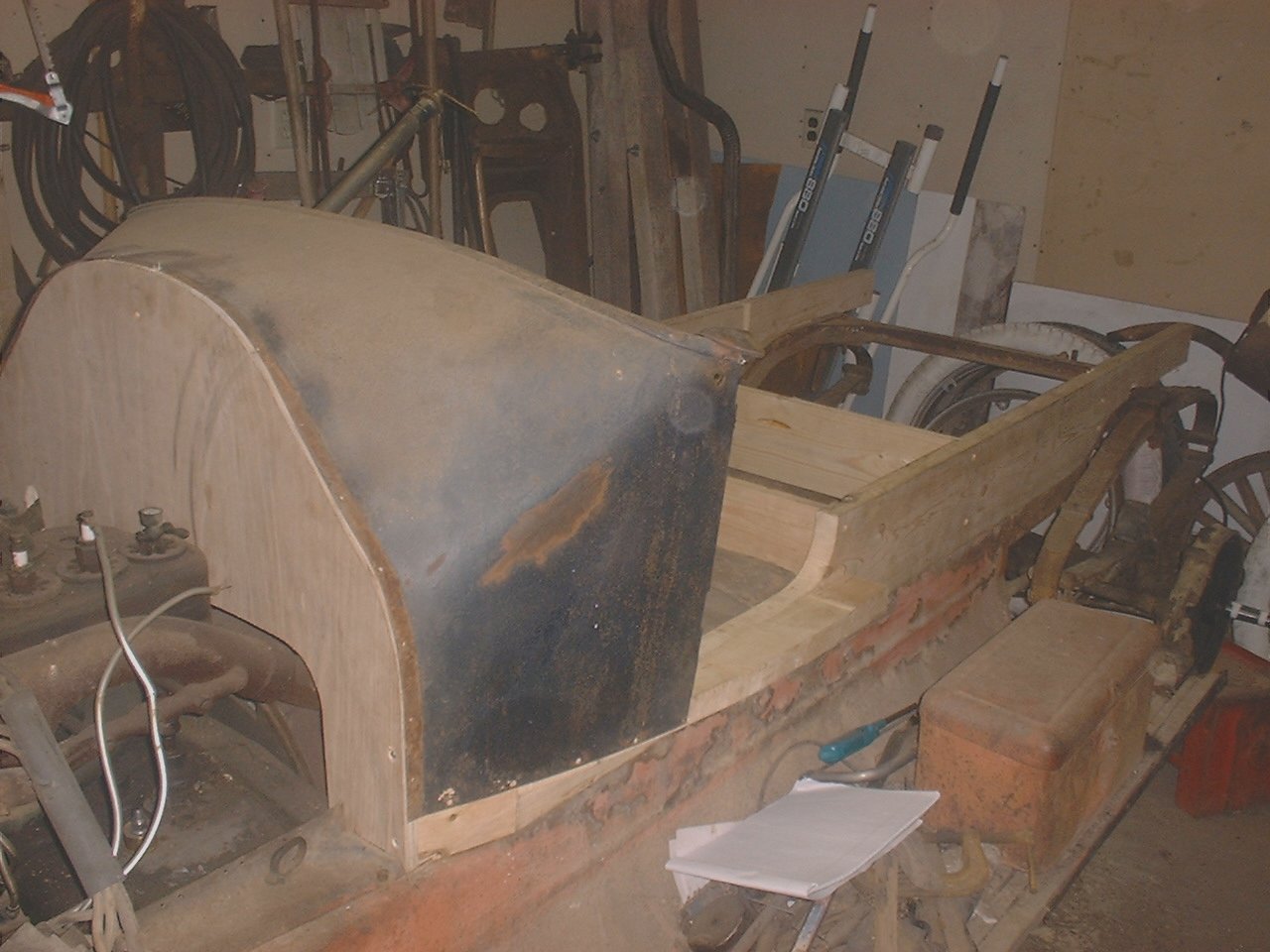 |  |
| Original Cowl metal being fit to new body. Click on the picture to see the full size. | The original floorboards almost fit. They are to big by 1/4". Click on the picture to see the full size. |
Monday, January 14, 2002 11:25 AM
 |  |
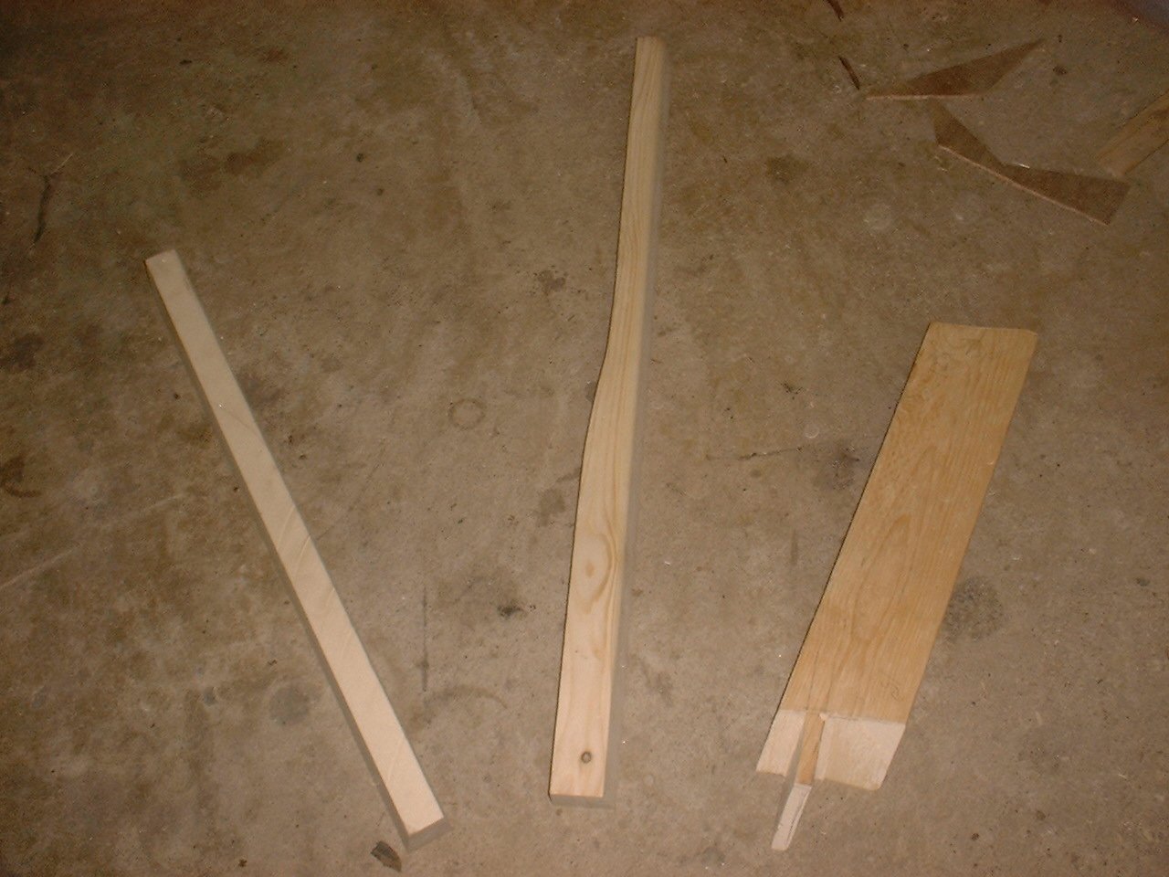
| New body with door fit. Click on the picture to see the full size. | The wood on the drivers side showing the door pillar (except there is not door on that side) and the hardest piece to cut up to this point (the angled piece). Click on the picture to see the full size. |
I got the cowl fit to the wood frame by trimming the firewall until the bottom edge of the metal cowl fit to the edge of a piece of wood I was trying to line up to. I then cut the door pillar for the passengers side (only one door in the front seat and that is on the passenger side). Initially I did not cut out for the door hinges, but cut everything else.
 |
| Here is the passenger side inside the cowl showing the door pillar, firewall, and the piece that goes between them. Click on the picture to see the full size. |
Here is a brief description of what I did: I took a 2x4 and laid it on top of the door pillar and firewall mounting block, both of which I had already cut the mortise for the tenon to go into. The mortises are open on one side, so they are really just a slot in the end of these boards. I then took a pencil and traced the shape of the mortise onto the 2x4 on both ends. I then chiseled a very shallow tenon into the 2x4 on both ends, just enough so that when I put the 2x4 back onto the door pillar and firewall support block, the small tenons would hold the board in place. I then took my angle finder (not official term) and measured all the angles for the tenons and transferred them to the 2x4. I was now able to cut the tennons with my handsaw. Now that the 2x4 fit into the door pillar and firewall support block, I was able to trim the rest of the board to fit under the cowl correctly. I basically looked at the original and made the same trimmings on the new piece. Long story short: After three tries, I got it. When I did the drivers side piece, I got it the first try. Check out the picture of all this wood above.
After finishing the passenger side door pillar and the equivalent pieces on the drivers side, I was ready to hang the passenger side door. Before I could do that I had to take the hinges off the original door and take them apart, clean them up and make sure they work. One thing I noticed was that the hinges were not worn at all. They were tight like they were new. I also decided to use the original wood in the front passenger side door since it has no rot and is in good shape. I will use Kwik Poly on it to seal it though. I fit the door hinges until the door hung like it should to clear the bottom sill.
Next it was on to the front seat. I started by taking a bunch of pictures of what little was left of the front seat. You can see the original pieces and the new pieces I cut by clicking on the links in the following table.
| Click on the description to see the picture. | |
| BEFORE | CURRENT (01/16/02) |
| The rear drivers side corner of the original seat frame. | The rear passenger side corner of the pine seat frame. |
| The bottom side of the rear drivers side corner of the original seat frame. | New wood in seat back showing seat frame and seat divider. |
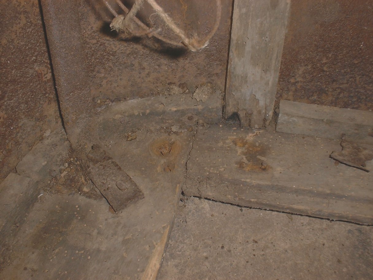
| The bottom side of the rear passenger side corner of the original seat frame. | The passenger side seat to lower body joint. |
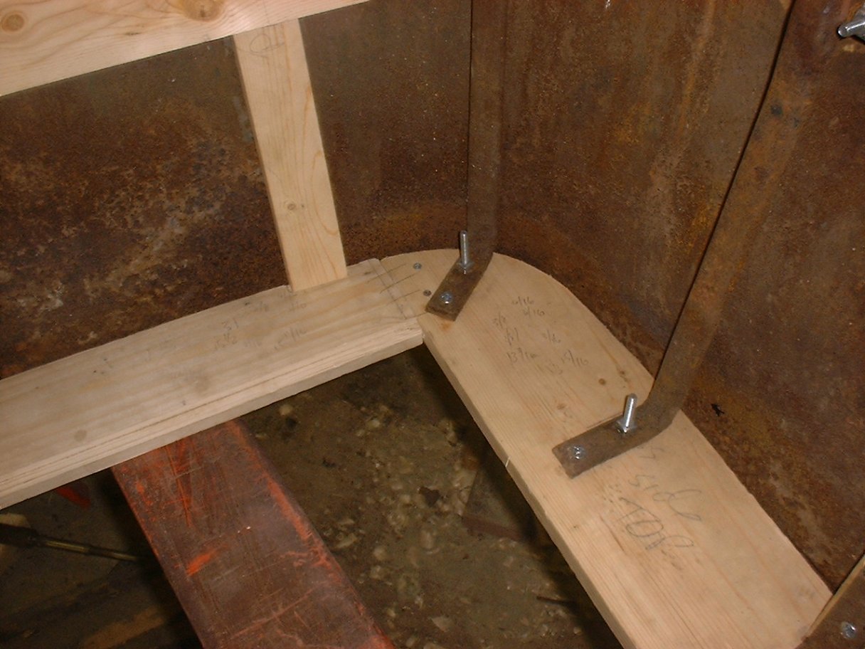
| "L" Bracket that supports the passenger side door frame on the seat. NOTE: This gave me the angle for this piece. | |
| Outside view of the door latch and frame that is part of the seat. | |
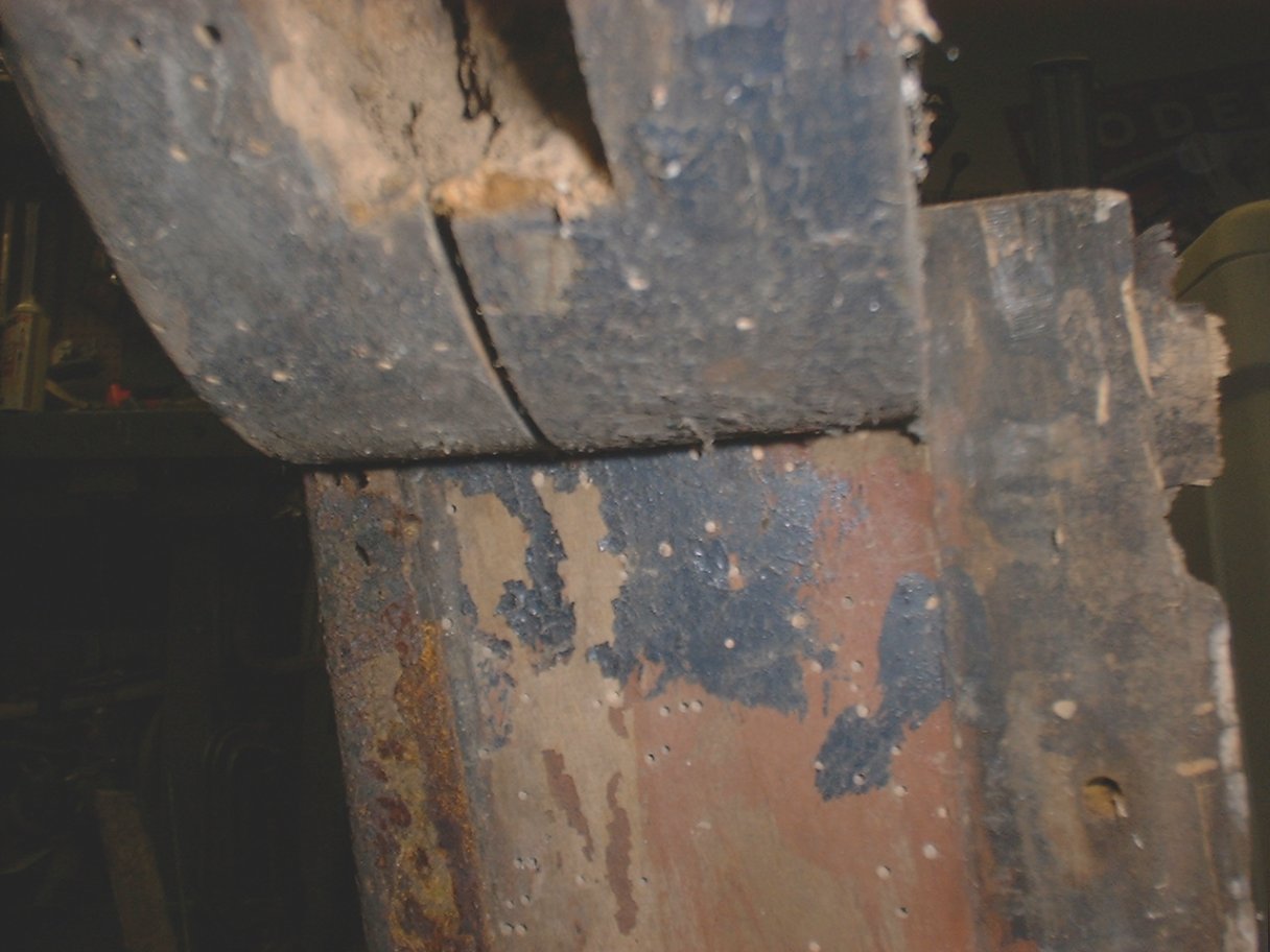 |
| Here is a look at the under side of the seat frame. NOTE the insect holes in the original wood. There was not much left. Click on the picture to see the full size. |
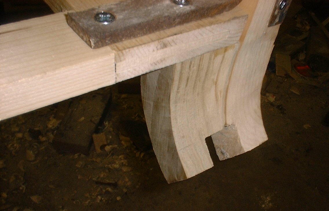
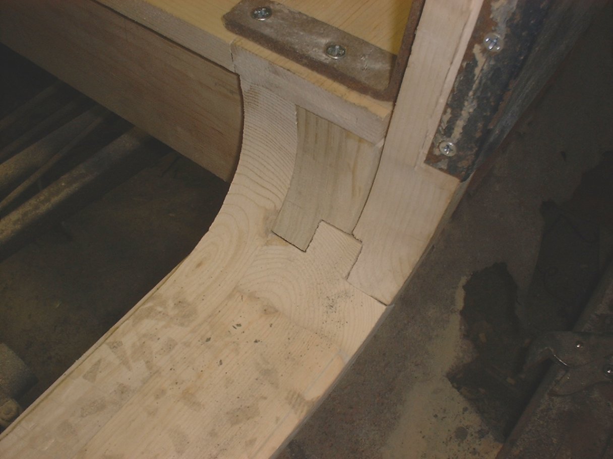 |
| Here is the tongue and groove joint between the seat and the lower body. It took a while to figure out how to cut this. Click on the picture to see the full size. |
When I got to the drivers side, I fit all of the pieces necessary to make the groove, and then cut the tongue to fit. After some sanding with the drum sander, I have a real nice looking joint.
 |  |
| See how well the passenger side door fits. Good as new. Click on the picture to see the full size. | Here is the framing for the door blank on the drivers side. Click on the picture to see the full size. |
So, all said and done, I have a door that clicks shut just like it should, the contour of the body looks really good and I am ready to finish the back end of the body base. That will require me to cut out for the rear seat, put in the rear seat kick board and put in the piece of wood that goes across the back of the car. I will also need to install the two pieces of flat steel that follow the curve cut out for the rear seat. the Tonneau sits on these flat pieces of steel.
I leave you in this entry (those who have stuck it out to this point) with pictures of each side of the body as of 01/12/02. See you later!
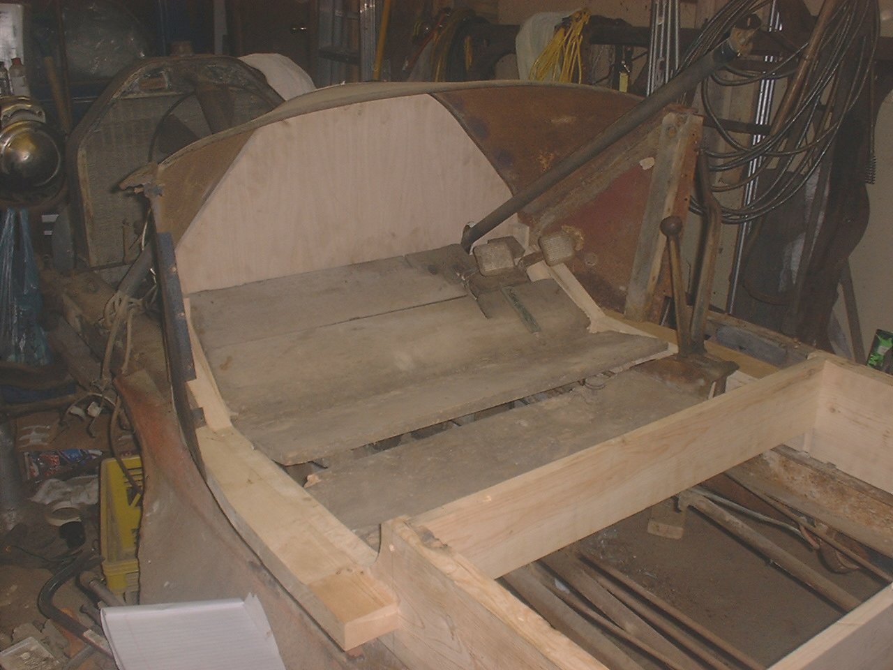
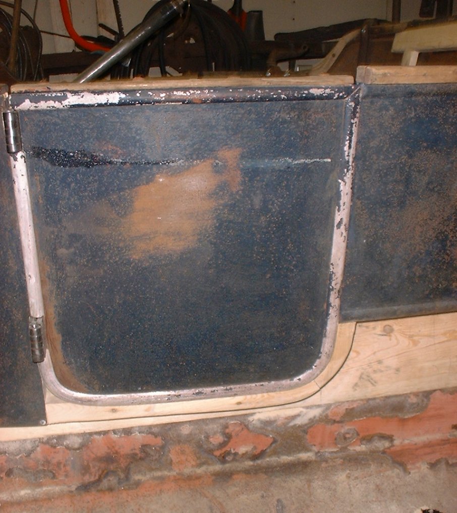
 |  |
| Passengers side of body as of 01/12/02. Click on the picture to see the full size. | Drivers side of body as of 01/12/02. Click on the picture to see the full size. |
Sunday, January 20, 2002 11:27 AM
 |  |
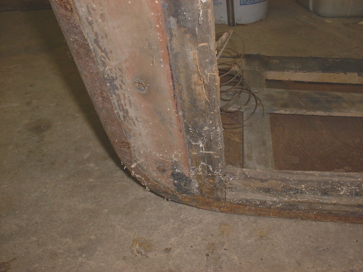
| The rear end of the body now cut out and ready to receive Tonneau. Click on the picture to see the full size. | The rear drivers corner sowing new steel added to steel rails that will support the Tonneau. Click on the picture to see the full size. |
I had to take the whole body apart from the point it was in the last entry so that I could cut out the area for the Tonneau from the main rails. I then had to fit the steel bars onto these areas I had cut out. These Steel bars are what the Tonneau sits on, so it is not wood-to-wood. The bar on the drivers side was short by about 5 inches. Looks to me like they came to the end of a piece of stock. There was probably a short filler piece that made up the difference, but it looks like it was lost at some point in the cars history. I looked at my neighbors car and both of his steel rails are one piece, so I added steel onto mine to make it the correct length. You can see a picture above.
I then fit the last piece of wood into the main part of the body this weekend. There was not anything very complicated about it. It is the piece that goes across the back of the car between the two main rails. It also has a piece of steel flat stock screwed onto it to support the Tonneau.
At this point, I am ready to start working on the Tonneau (back Seat). I have started a new page for the Tonneau since this page has gotten rather large. CLICK HERE to go to the Tonneau Resto Page.
As far as this part of the body, my next plan is to clean up and repair the metal, but I will wait until I have the Tonneau in the same shape as this part of the body. So it may be a while before I update this page again, several months at least.
Now, it is on to the Tonneau restoration.
Friday, May 24, 2002 11:28 AM
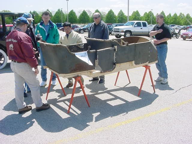 | 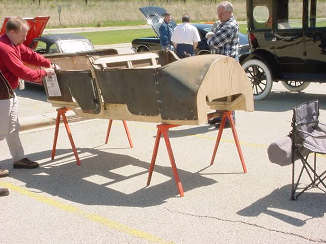 |
| Even just the body drew quite a crowd. Click on the picture to see the full size. | The body on horses at our Spring Noon time car show at work. Click on the picture to see the full size. |
Well, my E-M-F has been to it's first car show. So maybe it was only part of the car, but it was fun none the less and it attracted quite a bit of attention. I took the Model T (in the background in the pictures) and the body to work with me on Tuesday, May 21st 2002 to participate in our Spring lunch time car show. Between the two cars, I was busy the whole time answering questions, starting the T with the crank etc. It was fun.
Most peoples comments were "boy, what a lot of work". I think this gives people an appreciation for what it takes to make these cars look nice again.
Actual work on the car has been nonexistent. Hoping to get back on it a little after our Model T Tour next week.
Sunday, January 9, 2005 11:29 AM
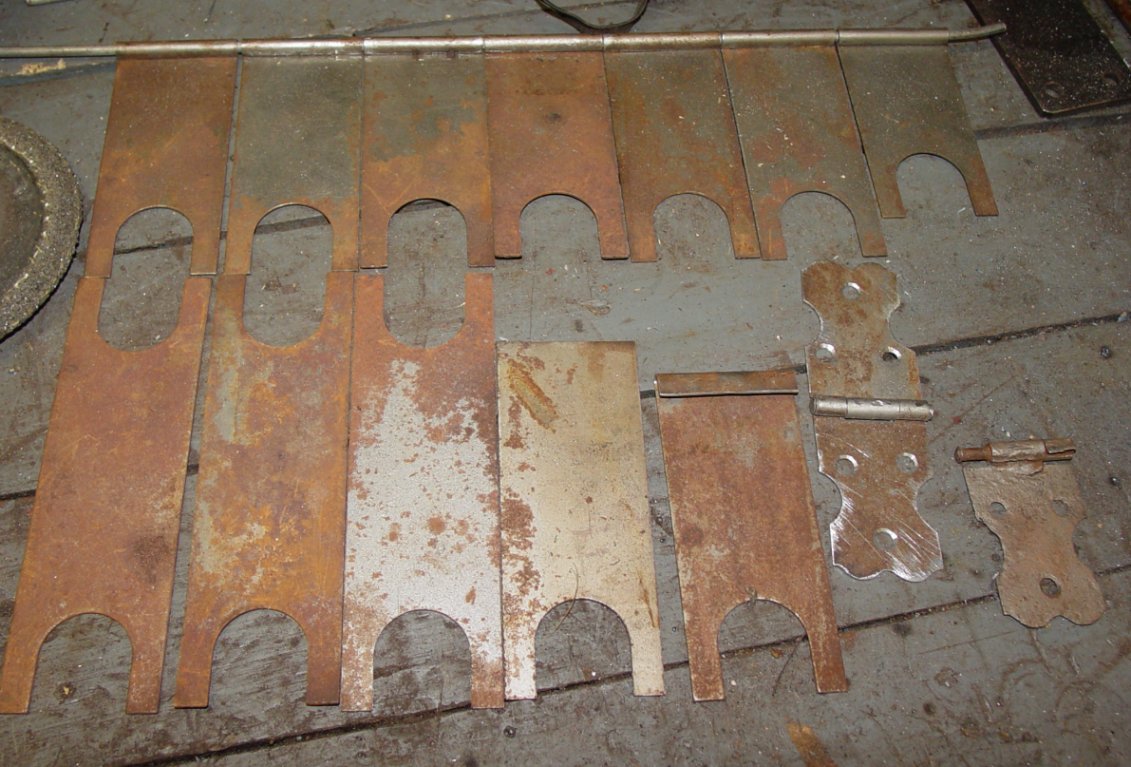 |
| Hinges and parts of hinges lined up on the bench. Click on the picture to see the full size. |
I finally figured out how to make new hinges for the panels under the seats. There are three "trap-doors" under the seats of this car to get at the gas tank in the front and a storage area under the back seat. The hinges on these panels were almost all gone on my car. If you look at the picture, the right most hinge parts in the bottom row is all I could find of a hinge (only half of one). But this was all I needed to know to build new ones, as long as I could figure out how to roll the metal to form the actual hinge part.
Well, after several failed attempts, I finally figured it out. The top row of hinge parts in the picture are the blanks I have made all connected with the hinge pin material, some heavy wire I had that was the same diameter as the original pins. The bottom row shows the pieces of steel I am using for blanks (first three from the left). I just happened to find a whole bunch of these in the garbage at my last job and took them home not knowing what I would ever use them for. They just happened to be the correct gauge for use in these hinges. It takes one blank per half hinge. I have just enough to make all the hinges I need and maybe one or two extra.
The forth one from the left on the bottom row is the first step, cut off one of the ends to start rolling the actual hinge. To roll the hinge, I took a piece of angle-iron the same thickness as the diameter of the hinge pin, ground off one side of the angel so I could clamp it in my vise, and then filed the edge round so I could form the first part of the roll. This was my jig. I could have used any piece of steel, but this piece of angle iron happened to be the first thing I found that was the correct size. Plus, I do not have a large selection of steel to choose from, mostly just scrap. In fact, most of you would probably laugh if you saw the stuff I keep to make things out of :).
I then placed the blank in the vise clamped against the jig with the correct amount of metal hanging over the edge so as to leave enough to finish the roll of the hinge. This was a trial an error thing until I found the right amount. Once clamped in the vise, I took a hammer and gently persuaded the metal around the jig to form a "J" figure. You can see a blank at this stage in the picture, 5th blank from the left on the bottom row. I was then able to remove the jig, put in its place a piece of the hinge material, and then finish folding the metal around the hinge pin with the hammer and a thicker piece of metal (the black piece of metal in the upper right hand corner of the picture).
After that, it was just some time with a die grinder, cutting wheel and file and I got the finished product, which is the 6th from the left in the bottom row.
So one more thing figured out. I had tried making a jig in a block of steel that consisted of a slot leading down to a hold where I had hoped I could force the metal to fold around the hole. It did not work. I tried a few other ideas also over the last couple of years until I found this method. The lesson is, "do not give up". I walk away from things and come back at other times until I figure things out.
That is all for this entry. Please let me know if you have any questions.
How to contact me... |

|
|
John M. Daly |
||
| Phone: | (815) 786-4824 | |
| Email: | ||